Friday 2 December 2011

Week 6 Editing and Animating 2

After having a group discussion and showing each other our animation file we created we each decided to make adjustments. I did some tweaking with the camera making the camera lens much smaller therefore allowing the camera to see more. This helped me knock some frames off of the frame count and made the camera look more zoomed out.

After tweaking the cameras for each of my animation files, I then moved on to adding some of the missing items. I first added the toilet signs to the doors which are found at the top of the stairs. I then added a few pictures around the guildhall, two in the library and one at the top of the stairs.

I also created a whiteboard which has been overlooked as an objected needed to be created for the guildhall. This was done by simply creating an editable poly box and using the inset tool to create a border around the front polygon. Next using the extrude tool to move the polygon back to show off the border. I then added a white material to it.

I then added a few lights around the guildhall. These are photometric lights and with Michaels help was able to create a few lights and place them around the guildhall, kitchen and library.
All of the windows were then rotated so that the detail in the window could be seen more clearly. I also added a few materials to the guildhall including a wooden material to each of the doors and wall paint to each of the rooms. All these are pre-set materials found within 3ds max. I then added the beams to the main guildhall, one running down the length of the room and another a bit lower across the width of the room. I added a smaller beam joining these two beams together.
I then added the projector into the room placing it in front of the whiteboard. This projector will be hanging from the lower support beam. A small cylinder is then placed between the projector and the beam to make it look as though the projector is hanging from the beam.
small chair
I decided to create a quick and simple chair, like the ones often found in a classroom. This chair will be placed inside where the services stairs should be found outside the kitchen. This is because this area is quite bare at the moment; it’s just an empty room between the guildhall and the kitchen.
A simple chair can be created by first creating an editable poly box and splitting it into segments. Next extruding out two rows of segments either side of the box and deletes the faces within them to create a hole. Patch up the gaps in the faces using the shift copy method to drag lines over the unwanted gaps. Extrude a row of segments out at the top of the box to form the back of the chair and move the vertices back a little. Apply a mesh smooth to make the chair look a little more rounded.
This chair can now be placed in the room next to the kitchen and copied a few times to look like multiple chairs.
Re-animate the last animation
Because of all the changes and things added to the guildhall the last scene needs to be re-animated so as to make sure that everything stays in the same place. These can be imported but the number of changes that have been made will make it much easier to re-do the last part. This scene just involves the camera moving back into the guildhall from the kitchen and then moving to face the whiteboard.
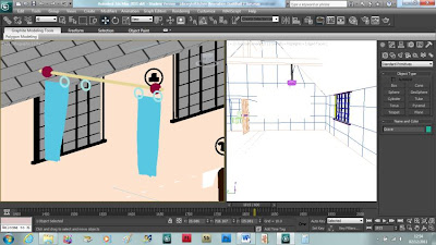
I also imported some curtains that we will use to end the animation, with the curtains closing in front of the camera. These curtains were made by me last year and they were done using the reactor method.

Friday 25 November 2011

Week 5 Editing and Animating

After having a group discussion we broke up a few more tasks for each of the group members. The first thing I needed to do was to go back to the library and kitchen and make the objects in there much bigger. After making everything bigger the whole room felt far too cramped so I decided to make the computer table much smaller and some of the book shelves smaller. I also deleted some of the bookshelves to create more space in the library.
For the kitchen everything just needed to be a little bigger and the fridge a little taller.

I then moved on the floor design mapping out each of the group members animation path. Each section has a start and cut off point, each cut off point is in a position that is easy to continue a camera path from a different group member. For example Michael rotates the camera around the guildhall then zooms into the entrance of the guildhall cutting off in front of the shop door. The shop door is where Troy will pick up the animation path. This allows each of us to work on a portion of the animation at the same time. We can then import all of the animation paths and cameras into one file and then tweak the points between each of the separate animations allowing them to run much smoother.

My path is from the library door to the guildhall door after visiting kitchen via the guildhall.

The first part of my animation will just involve the camera entering the library and moving along a path round the library then back to the door. The camera will then move along the glazed walkway slightly and then stopping in front of the stair case leading up to the guildhall.

To start create a camera and create a path for the camera using the line tool. In the animation drop down bar select path constraints and attach the camera to the path. The camera will now move along this path. Using the auto key function move the target of the camera so that each part of the room is closely viewed as the camera moves along the path.

At the start of the animation set the pivot point on the door to the side, then in auto key rotate the door so that it moves out the way of the camera. This gives the illusion that the door is on a set of hinges.

Move the points of the path around if need be and extend the time frame of the animation to make the animation longer. This has been set to 800 frames which is roughly 25 seconds.

The points of the path need to be moved a little so that the camera doesn’t go through the wall.
The next part of the animation is moving the camera up the stairs. This can be done by creating a new camera and placing it in the exact same position as the other camera, then moving it up the stairs along a timeline. It is very hard to create a path for the camera as it is moving up the stairs, so this is done free – hand. This part of the animation lasts 300 frames which is about 10 seconds long and ends in front of the guildhall door. The next part of the animation will start where this one ended.

The next part of the animation starts off where the last ended, in front of door leading into the guildhall.

The animation will start with the door opening into the guildhall with the camera following a path leading to the back of the guildhall where the kitchen is located. The door to the landing then opens as the camera passes through where the camera then turns towards the kitchen door. The kitchen door then opens and the camera goes inside, rotating around the room looking at all of the appliances.

The last part of the animation is from the kitchen moving back into the guildhall and facing the wall with the whiteboard on it. The animation starts from the same point the last animation stopped at so as to keep the flow of the animation together. The kitchen door opens again followed by the door leading into the guildhall. The camera then moves up to the ceiling looking at the beams, then down towards the wall and pausing. From here the projector starts playing some images and the curtains round off the animation. The curtains and projector have yet to be added to this part of the animation yet.

We have also decided to use a couple of bipeds to walk around the guildhall making the whole place feel less ghostly. This is will be done next week along with the lighting and the shadows and also the curtains for the end animation.

Friday 18 November 2011

Demonstration of New Skill

Creating all these objects has helped me further my skill set in 3DS Max. The key tool I have learned is probably the connect tool which has been a valuable tool for nearly all of my objects. Before discovering this tool I just used the cut tool to create a new polygon or separate polygons from one another. The connect tool lets me do this but also lets me create evenly spaced polygons so that I don’t have to guess how far apart polygons are from one another. The key object where this is most easily demonstrated is the bookcase. Each shelf is evenly spaced apart from one another as a real bookcase should be using the connect tool then extruding them inwards.

Week 4 Object Creating and Editing

Inside door

After having a discussion we came up with a few more objects that need to be created for the guildhall. The first is the door, a door found on the inside of the guildhall which will be very different from the ones found on the outside.

To start create an editable poly box and use the inset tool to create a border around the door. Next use the connect tool to cut up the door frame into a few sections. Use the inset tool again on each of the sections to create small borders to show off the door patter. Select the small faces around each of the new faces created using the inset tool and extrude those inwards slightly.

Next using the symmetry modifier will help mirror the door so that this new pattern appears on the other side of the door.

For the door handle create and editable poly cylinder and apply the bend modifier tool. Place on the door and then apply the reflection map with the raytrace feature which will give the handle a chrome effect. The symmetry modifier can also be applied here to create a door handle on the other side of the door.

Glazed door

For this take the inside door already created and place a glass effect using the refraction and raytrace map in the sections that have been split up using the inset and connect tool. Use the symmetry modifier to apply the same to the other side of the door.

Fireplace

After completing the layout for the library I suddenly realized that we had overlooked another object, the fireplace.

To start create an editable poly box and add some segments to it, then remove some of the bottom front faces, this will form the space in the fireplace. Next select all of the lines around the outside of the space and use the shift copy method to draw out some new lines. Move these lines inwards towards the back of the fireplace then extrude the top ones upwards a little to create the chimney. Flip the bottom segments around then extrude them upwards a little to create a platform where the logs will sit.

Create a cylinder and add a tree texture to it. Copy it several times, sort them into a pyramid shape then place them in the new space on the platform.

Now the fireplace needs a grate/grill in front of it. Create and editable poly cylinder and move the vertices near the top of the cylinder back a little making a curve shape. Use the shift copy method to create several copies and place them in a row to form the grate.

Now that the fireplace is complete I can add it to the library with all of the other objects organised last week. I also gave it a marble look to resemble a more realistic fireplace.

I have also updated the group blog with all of the modelling techniques that have been used amongst the group members. This helps us keep track of what different techniques each of us have tried. I have also updated the group blog with animating techniques that we could use when we reach the animating stage. These techniques include camera movement, lighting and shadowing and also toying with the idea of using the reactor tool to create curtains.


Bannister Pole

Next a bannister pole is needed for the stair case. This is quite a simple object to create, first use the line tool and create a long shape, with a few bumps here and there in the front viewport. Next use the lathe tool around the y axis to create a 3d shape. Open vertex mode in the line modifier and make sure that show end result is turned on. From here any changes to the vertex can be made and clearly show what the shape will look like when finished.

Friday 11 November 2011

Week 3 Object Creating and Room Layout

Kitchen cupboard

After having a brief discussion we came up with a few more objects that we can model to illustrate each room better. The first thing I chose is a kitchen cupboard which can be placed next to the sink, or on the wall somewhere. To start create an editable poly box and use the inset tool to create an outer edge to the box. Next use the connect tool to split up the bigger polygon into two smaller polygons, this will make a two door cupboard. Next extrude the two polygons inwards slightly to show off the edges of the two doors. To create a handle use the line tool to create a semi-circle shape then use the lathe tool to make it 3D. Copy the handle and attach both to the cupboard, so that when the cupboard is moved the handles move with it.

Fridge
The next object is a fridge which will also be placed within the kitchen. To start create an editable poly box and use the inset tool to create an outer frame then extrude the polygon inwards slightly which will help show off the door. Next use the connect tool to create a small thin horizontal polygon across the large polygon which will be the door. After that use the connect tool again to create a smaller polygon within the polygon just created, and moved over to one side. Extrude this small polygon to create a block handle. Use the inset tool on either side of the newly extruded polygon then delete the face; this creates a space for the handle.

Now that I have created a few more objects to go in the kitchen I can now start laying out the rooms using the objects we have created.


The library

First I am going to create the layout for the library. The library will include a table, sofa, computer and chair, printer, bookcase and maybe a few picture frames scattered about the room once the room has been placed into the guildhall.

Using the image below which shows a rough sketch of the guildhall room plans we can make out what the room make look like.


First take the bookcase and place in onto the plane, which will act as the base and area of the room. The bookcase can be copied a few times and placed about the room to form a few isles. They can also be stretched a little to make them seem longer bookcases if necessary.


To line the book cases up as best as possible enter the top viewport so that it is easier to see the layout of the room.
Next take the sofa and the computer chair and place them around the other side of the room, slightly away from the bookcases.

They will also need resizing and moving around slightly. Once one is the correct size using the shift copy method crate another of each the sofa and the chair and place them around the room sticking to a rough plan of the guildhall.
Next import the table and computer which will be placed corresponding with the computer chair. Resize them to match the computer chair as closely as possible then place in the library. Also use the shift key to create an extra table, scale it down and place it in-between the two sofas.
Extend out one of the sofas to make it longer by using the scale tool. The arms may appear to thick now that it’s been scaled so in vertex mode move the lines out a little more so that the sofa keeps its length without affecting the arms of the sofa.
Also move the chair, computer and table furthest from the book case. Move it so that it’s still facing the same direction but against the wall just before the dent in the room.
Next import the cupboard which will be placed under the stairs and the printer. The cupboard for now can rest in the space outside of the room as it will fit underneath the stair case within the guildhall. The printer can be placed near the wall next to one of the computers.
Once everything has been placed within the room make sure that all objects have been linked to the plane. This will allow everything to be moved at once by only moving the plane without having to select everything individually.
Stove
Next take one of the kitchen cupboard copies, delete the handles and rotate it to its standing on its side.  Use the connect tool on the top polygon to split it up into two separate polygons. Use the inset tool to give spacing between the new polygons, that way they will no longer affect each other when editing the polygons. Select all four sides from one polygon and use the connect tool again to create a square in the middle. Next select all of the individual vertices from the square now created and use the chamfer tool which will round the edges of the square.
Extrude the faces out a little bit then give them a different coloured map, such as black to show of the hob. Give the two windows at the front a dark colour as well to show off the oven.
Now onto the kitchen. The kitchen will contain the fridge, cupboard, sink and table. There may be a few other smaller things that need to be created such as hooks for coats once the room has been placed inside the guildhall.
Using the image below which shows a rough layout of the rooms we can map out the kitchen.
The kitchen
First import the fridge and scale it down a little so that it doesn’t appear too big in the kitchen. Place the fridge on the outer edge of the kitchen.
Next import the kitchen cupboard which will be copied a few times so as to make it look as much like a side board than a cupboard.
Import the table and place roughly in the middle of the room. This table will have a whiter colour than a wooden colour.
Import the sink and place towards the back of the room. Some sort of sideboard will need to be created so that the sink can fit into it.
Create an editable poly box which a number of segments. This box will be used as the basin for the sink. Some adjustments to the box may need to be done to allow the sink to fit comfortably, such as deleting a few segments at the top of the box. Copy the basin and the sink and place it on the other side of the fridge. This sink is shown on the designs but it may be removed before final rendering.
Lastly import the stove and place next to the kitchen cupboard.
Make sure that all of the objects are linked to the plane to allow for easy movement.

Friday 4 November 2011

Roof

The roof for the guildhall is quite a bit more complex compared to the objects that I have been modelling. For this I needed the measurements from the guildhall which was given to me by Michael, using a plane as a base, so that the roof can be put on top of it. Next create a very thin editable poly box and rotate it 45 degrees, then using the rotate tool and holding down the shift key create another box. Put these two boxes together to form the triangular roof. Next create a very thin cylinder and place it at the top of the roof, filling in the gap between the two roof panels. Create two panels either side of the roof to make the roof whole. Next split each box up into segments and remove one from each side, opposite each other. Select vertex mode and move the two points down onto the outer corner of the segment to form a triangle shape. Create another editable poly box and join it to both of the roof boxes. Lastly in the material editor, move down to the map section, click on bump map and select the tile map. Set the parameters and choose the appropriate colour scheme and add to the roof.

Week 2 Object Creating and Materials

Glass Cabinet

The glass cabinet is an object that will be placed within the museum, holding various interesting items the public can view. First off create a box and convert it to an editable poly. Using the connect tool draw lines around the outer edge to give it a frame. Next use the extrude tool to move the big panel inwards a little so that the outer frame is more noticeable. Using the connect tool again create a smaller rectangle about a quarter of the way from the bottom, then again cutting it in half. Using the inset tool next, select these two faces and move them inwards slightly, forming another outer frame. Next using the line tool, create a semi-circle shape, then use the lathe tool, this makes the semi-circle repeat itself in a 360 degrees, forming a handle shape. This is then fitted onto the cupboard. Use the link tool to connect the handle to the cupboard so whenever the cupboard is moved, so is the handles.

Glass Display Stand
The glass display stand will be similar to the glass cabinet, in that it will contain interesting and related items. To start create a box and convert it to an editable poly. Next use the connect tool to form an outer edge, then extrude the top of the box moving it inwards slightly. After that select one side of the box and move it down, so that the front is higher than the back. Next, imports the table previously created and place the new box on top.

Computer
The computer will be placed within the library of the guildhall. It is another fairly simple item that is created by once again creating a box and converting it to an editable poly. Using the connect tool again forming an outer frame and extrude tool pushing the polygon inwards. Next using the connect tool again forming a smaller face at the bottom of the box, which is then extruded to form a beginning to the base of the computer. The connect tool is then used again to create a smaller face which is once again extruded to create the base of the computer.
Chair
The chair is a more complex object to create, as it is made up from several parts which need to be linked, opposed to most other objects that have been created using only one object. Once again though to start first created an editable poly box and use the connect tool to create a smaller polygon at the back of the box. This box can then be extruded upwards to form the back of the chair. Using the connect tool again create multiple lines, then select every other polygon and delete them. This creates gaps as often seen in wooden chairs.
Next using the connect tool and chamfer tool, create another small polygon in the centre underneath the chair. This polygon can then be extruded to form the pivot point of the chair. The polygon at the bottom is then bevelled out, then the polygon deleted. Now selecting every other line around the deleted area of the bevelled polygon, holding the shift key create some new lines. This forms spaces around the base, where the legs of the chair can be fitted.
Now create another box, convert it to an editable poly and fit it in one of the new spaces around the base of the chair. Copy the box and
Lastly create a small sphere and place it underneath the leg of the chair, copying it around for the other legs.
I also decided to add some arms to the chair using the extrude tool. This is done by selecting the seat of the chair and extruding out the sides a little, then extruding the new polygon at the top to make two blocks. Using the connect tool again create some lines around the outer edge of each of the blocks, and then delete the polygon in the centre to form a hole in the chair arms.
place it in all of the other spaces around the base of the chair.

 
Various materials
As a group we decided to go for a woody effect as a whole so for this we researched and found a few wooden textures using Google images.
For a number of my objects I need a glassy effect as well, particularly for the display cabinet and stand. This is done by going to the maps, in the material editor, clicking on the refraction option and choosing the raytrace material. This creates a glass effect; the parameters can then be set to see how see-through it can be. To add chrome effects click on the reflection button instead and choose raytrace. Below are a few rendered images on created objects with their appropriate maps:
Printer
The next object to create is the printer, which will be placed in the library alongside the computer. To start create an editable poly box and using the connect tool to make some lines across the sides of the box. Next inset these lines to form an outline and extrude them slightly, to show off the edges.
Use the inset and connect tool again to form two small polygons at the top of the top. Extrude the smaller one upwards and delete the polygon to the side to make a hole. Extrude the bigger one downwards slightly to form a tray. Use the connect tool again to create a small panel at the front of the printer.
Lastly add some materials to it, a creamy colour for the printer and a green colour to show where the display panel will go.
Cupboard
The cupboard is another very easy item to model. Get an editable poly box, select the front face and inset, then extrude it inwards slightly. Then use the lathe tool to create a handle just like for the glass display cabinet. Finally make sure that the handle is linked to the cupboard.
Shop counter
For this I used the glass cabinet that I had already created. I shrank the top down to make it much smaller and deleted the handles off of the cabinet.
Lantern
The lantern is also another easy item to draw. First start off with an editable poly box, select all of the faces round the outside and inset them a little, then extrude those inwards slightly. Next use the lathe tool to create a light bulb. Finally select the four extruded faces and apply a glass material so that you can see into the lantern.